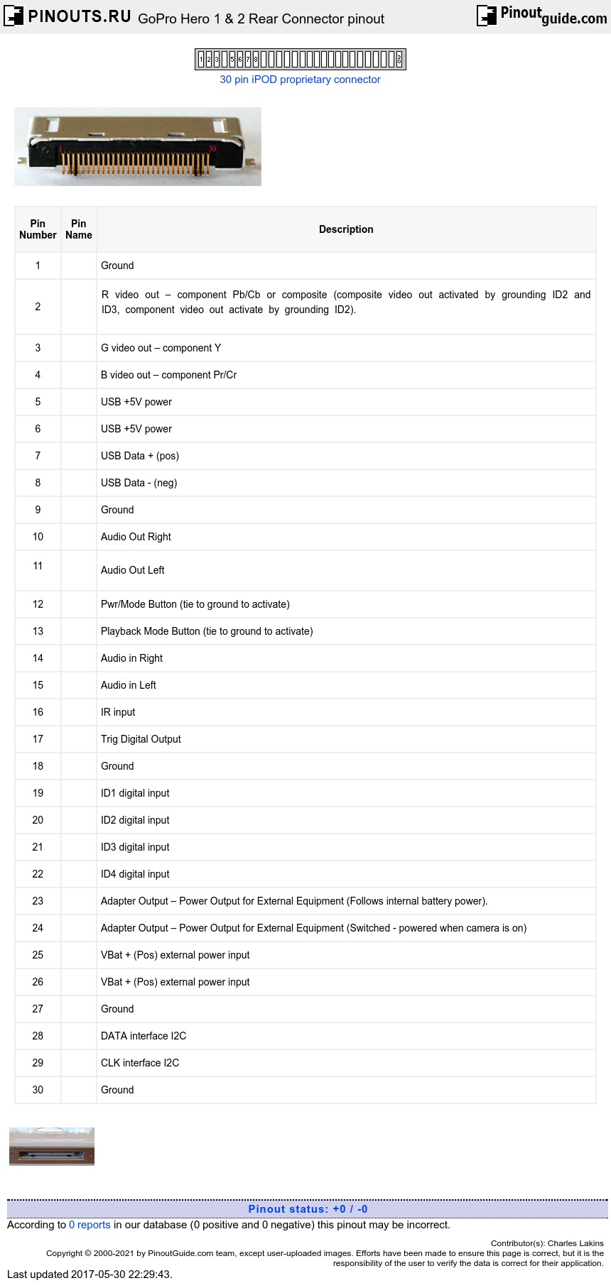
Socket

Connector

Rear Of Connector

| Pin Number |
Pin Name |
Description |
|---|---|---|
| 1 | Ground | |
| 2 |
R video out – component Pb/Cb or composite (composite video out activated by grounding ID2 and ID3, component video out activate by grounding ID2). |
|
| 3 | G video out – component Y | |
| 4 | B video out – component Pr/Cr | |
| 5 | USB +5V power | |
| 6 | USB +5V power | |
| 7 | USB Data + (pos) | |
| 8 | USB Data - (neg) | |
| 9 | Ground | |
| 10 | Audio Out Right | |
|
11 |
Audio Out Left | |
| 12 | Pwr/Mode Button (tie to ground to activate) | |
| 13 | Playback Mode Button (tie to ground to activate) | |
| 14 | Audio in Right | |
| 15 | Audio in Left | |
| 16 | IR input | |
| 17 | Trig Digital Output | |
| 18 | Ground | |
| 19 | ID1 digital input | |
| 20 | ID2 digital input | |
| 21 | ID3 digital input | |
| 22 | ID4 digital input | |
| 23 | Adapter Output – Power Output for External Equipment (Follows internal battery power). | |
| 24 | Adapter Output – Power Output for External Equipment (Switched - powered when camera is on) | |
| 25 | VBat + (Pos) external power input | |
| 26 | VBat + (Pos) external power input | |
| 27 | Ground | |
| 28 | DATA interface I2C | |
| 29 | CLK interface I2C | |
| 30 | Ground |


 correct
 incorrect