

| Pin Number |
Pin Name |
Description |
|---|---|---|
| 1 | Empty | Not used |
| 2 | GND | Red Wire - Connected to Yellow wire on PCB 0 volts |
| 3 | +24v | Black Wire - Connected to +24v Input on PCB |
| 4 | Empty | Not used |
| 5 | GND | Yellow wire - Connected to Red wire on PCB - 0 vots |
| 6 | Switch | On/Off Switch - normally open when OFF |
| 7 | Switch | On/Off Switch - shorted to pin 6 when ON |
| 8 |
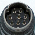
I have taken the unit apart to get this information and just chopped off the plug since I did not have a suitable connector for it. The wires into the plug are all coloured as above so you can apply 24v between the Black wire (+ve) and red or yellow (-ve). The switch is not connected inside the unit but is used to tell the scanner to turn on the 24v. I joined the Black and Brown wires together and applied 24v to the Orange (+ve) and Red+Yellow (-ve) so the switch now works.
 correct
 incorrect