60 Pin1 |
Signal |
25 Pin |
Signal |
Direction DTE DCE2 |
|---|---|---|---|---|
| J1-11 J1-12 |
TxD/RxD+ TxD/RxD- |
J2-2 J2-14 |
BA(A), TxD+ BA(B), TxD- |
 |
| J1-28 J1-27 |
RxD/TxD+ RxD/TxD- |
J2-3 J2-16 |
BB(A), RxD+ BB(B), RxD- |
 |
| J1-9 J1-10 |
RTS/CTS+ RTS/CTS- |
J2-4 J2-19 |
CA(A), RTS+ CA(B), RTS- |
|
| J1-1 J1-2 |
CTS/RTS+ CTS/RTS- |
J2-5 J2-13 |
CB(A), CTS+ CB(B), CTS- |
|
| J1-3 J1-4 |
DSR/DTR+ DSR/DTR- |
J2-6 J2-22 |
CC(A), DSR+ CC(B), DSR- |
|
| J1-46 J1-47 |
Shield_GND MODE_2 |
J2-1 - |
Shield - |
Shorted |
| J1-48 J1-49 |
GND MODE_1 |
- - |
- - |
Shorted |
| J1-5 J1-6 |
DCD/DCD+ DCD/DCD- |
J2-8 J2-10 |
CF(A), DCD+ CF(B), DCD- |
|
| J1-24 J1-23 |
TxC/RxC+ TxC/RxC- |
J2-15 J2-12 |
DB(A), TxC+ DB(B), TxC- |
|
| J1-26 J1-25 |
RxC/TxCE+ RxC/TxCE- |
J2-17 J2-9 |
DD(A), RxC+ DD(B), RxC- |
|
| J1-44 J1-45 |
LL/DCD Circuit_GND |
J2-18 J2-7 |
LL Circuit_ GND |
- |
| J1-7 J1-8 |
DTR/DSR+ DTR/DSR- |
J2-20 J2-23 |
CD(A), DTR+ CD(B), DTR- |
|
| J1-13 J1-14 |
TxCE/TxC+ TxCE/TxC- |
J2-24 J2-11 |
DA(A), TxCE+ DA(B), TxCE- |
|
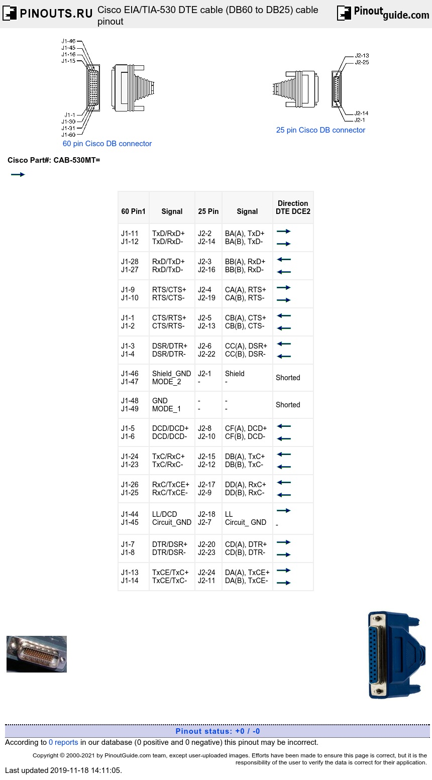
Arrows indicate signal direction: indicates DTE to DCE, and indicates DCE to DTE.
1 Any pin not referenced is not connected.
2 The EIA-530 interface cannot be operated in DCE mode. A DCE cable is not available for the EIA-530 interface.
 correct
 incorrect