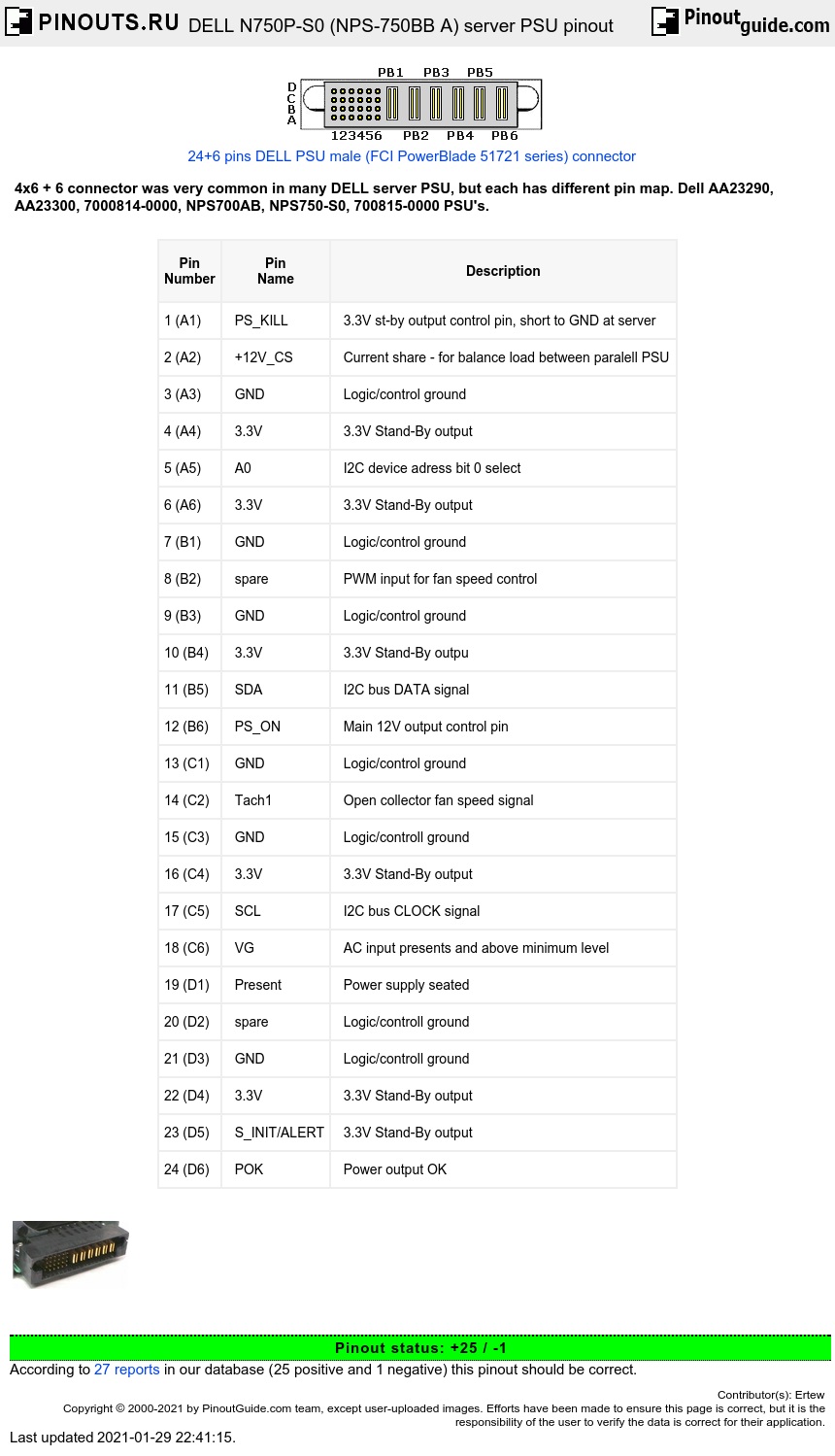
Controll pins:
| Pin Number |
Pin Name |
Description |
|---|---|---|
| 1 (A1) | PS_KILL | 3.3V st-by output control pin, short to GND at server |
| 2 (A2) | +12V_CS | Current share - for balance load between paralell PSU |
| 3 (A3) | GND | Logic/control ground |
| 4 (A4) | 3.3V | 3.3V Stand-By output |
| 5 (A5) | A0 | I2C device adress bit 0 select |
| 6 (A6) | 3.3V | 3.3V Stand-By output |
| 7 (B1) | GND | Logic/control ground |
| 8 (B2) | spare | PWM input for fan speed control |
| 9 (B3) | GND | Logic/control ground |
| 10 (B4) | 3.3V | 3.3V Stand-By outpu |
| 11 (B5) | SDA | I2C bus DATA signal |
| 12 (B6) | PS_ON | Main 12V output control pin |
| 13 (C1) | GND | Logic/control ground |
| 14 (C2) | Tach1 | Open collector fan speed signal |
| 15 (C3) | GND | Logic/controll ground |
| 16 (C4) | 3.3V | 3.3V Stand-By output |
| 17 (C5) | SCL | I2C bus CLOCK signal |
| 18 (C6) | VG | AC input presents and above minimum level |
| 19 (D1) | Present | Power supply seated |
| 20 (D2) | spare | Logic/controll ground |
| 21 (D3) | GND | Logic/controll ground |
| 22 (D4) | 3.3V | 3.3V Stand-By output |
| 23 (D5) | S_INIT/ALERT | 3.3V Stand-By output |
| 24 (D6) | POK | Power output OK |
Warning: Controll interface was 3.3V only. Do not connect to 5V circuit.
| Pin number | Description |
|---|---|
| PB1 | GND return for main output |
| PB2 | GND return for main output |
| PB3 | GND return for main output |
| PB4 | +12V main output |
| PB5 | +12V main output |
| PB6 | +12V main output |
Seems to be the same pinout for a Z750P, which is very similar to N750P (also a 750W supply).
Seems to be the same pinout for a Z750P, which is very similar to N750P (also a 750W supply).
Also, it would make more sense that there would be ~20A max per rail, given it's a 60A power supply, with a 30A absolute maximum.
Notes:
Connect A1 to GND (jumper to B1) for run 3.3V st-by supply.
Connect B6 to GND (jumper to C1) for run main 12V output. Work only when 3.3V supply work.
Connect B2 to GND (jumper to B3) for slow down fan. PSU fan was designed to cooling part of server. By default, work at full speed.
SDA and SCL can be connected to SMB or I2C bus for identify PSU. Probably it's possible to remote controll supply or read working paremeters by that bus.
Server power supplies was wery powerfull beasts. Most of it have single +12V power output and single aux/st-by output.
N750P have 750W total output power:
3V3 @ 5.5A (18W)
12V @ 62.4A (748W)


 correct
 incorrect