USB type-C cable
Full-featured USB-C cables that implement USB 3.1 Gen 2 can handle up to 10 Gbit/s data rate at full duplex. They are marked with a SuperSpeed+ (SuperSpeed 10 Gbit/s) logo. There are also USB-C cables which can carry only USB 2.0 with up to 480 Mbit/s data rate. All USB-C cables must be able to carry a minimum of 3 A current (at 20 V, 60 W) but can also carry high-power 5 A current (at 20 V, 100 W). Full-featured USB Type-C cables are active, electronically marked cables that contain a chip with an ID function based on the configuration data channel and vendor-defined messages (VDMs) from the USB Power Delivery 2.0 specification. USB Type-C devices also support power currents of 1.5 A and 3.0 A over the 5 V power bus in addition to baseline 900 mA; devices can either negotiate increased USB current through the configuration line, or they can support the full Power Delivery specification using both BMC-coded configuration line and legacy BFSK-coded VBUS line.
Alternate Mode dedicates some of the physical wires in the Type-C cable for direct device-to-host transmission of alternate data protocols. The four high-speed lanes, two sideband pins, two USB 2.0 pins and one configuration pin can be used for Alternate Mode transmission. The modes are configured using vendor-defined messages through the configuration channel.
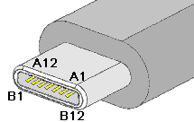
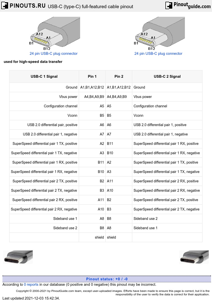
| USB-C 1 Signal | Pin 1 | Pin 2 | USB-C 2 Signal |
|---|---|---|---|
| Ground | A1,B1,A12,B12 | A1,B1,A12,B12 | Ground |
| Vbus power | A4,B4,A9,B9 | A4,B4,A9,B9 | Vbus power |
| Configuration channel | A5 | A5 | Configuration channel |
| Vconn | B5 | B5 | Vconn |
| USB 2.0 differential pair 1, positive | A6 | A6 | USB 2.0 differential pair 2, positive |
| USB 2.0 differential pair 1, negative | A7 | A7 | USB 2.0 differential pair 2, negative |
| SuperSpeed differential pair 1 TX, positive | A2 | B11 | SuperSpeed differential pair 1 RX, positive |
| SuperSpeed differential pair 1 TX, negative | A3 | B10 | SuperSpeed differential pair 1 RX, negative |
| SuperSpeed differential pair 1 RX, positive | B11 | A2 | SuperSpeed differential pair 1 TX, positive |
| SuperSpeed differential pair 1 RX, negative | B10 | A3 | SuperSpeed differential pair 1 TX, negative |
| SuperSpeed differential pair 2 TX, positive | B2 | A11 | SuperSpeed differential pair 2 RX, positive |
| SuperSpeed differential pair 2 TX, negative | B3 | A10 | SuperSpeed differential pair 2 RX, negative |
| SuperSpeed differential pair 2 RX, positive | A11 | B2 | SuperSpeed differential pair 2 TX, positive |
| SuperSpeed differential pair 2 RX, negative | A10 | B3 | SuperSpeed differential pair 2 TX, negative |
| Sideband use 1 | A8 | B8 | Sideband use 2 |
| Sideband use 2 | B8 | A8 | Sideband use 1 |
| shield | shield |
Coaxial wire construction should be used for all SDP’s and there are no drain wires. The shields of the coaxial wires are connected to the ground pins. If shielded twisted pair is used, then drain wires are needed and shall be connected to the GND pins. Pin B5 (Vconn) of the USB Type-C plug shall be used in electronically marked versions of this cable.
Pins B6 and B7 should not be present in the USB Type-C plug.
All Vbus pins shall be connected together within the USB Type-C plug. A 10 nF bypass capacitor is required for the Vbus pin in the full-featured cable at each end of the cable.
Shield and all GND shall be connected within the USB Type-C plug on both ends of the cable assembly.
Maximum cable length is 2 meters.
The USB Type-C Power-Only plug is a depopulated version of the USB Full-Featured Type-C plug or the USB 2.0 Type-C plug. Contacts for configuration channel, Vbus, and GND (i.e., A1, A4, A5, A9, A12, B1, B4, B9, and B12) shall be present, others are optional. Implementation of resistor or CC communication on pin A5 is required.


 correct
 incorrect