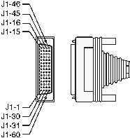
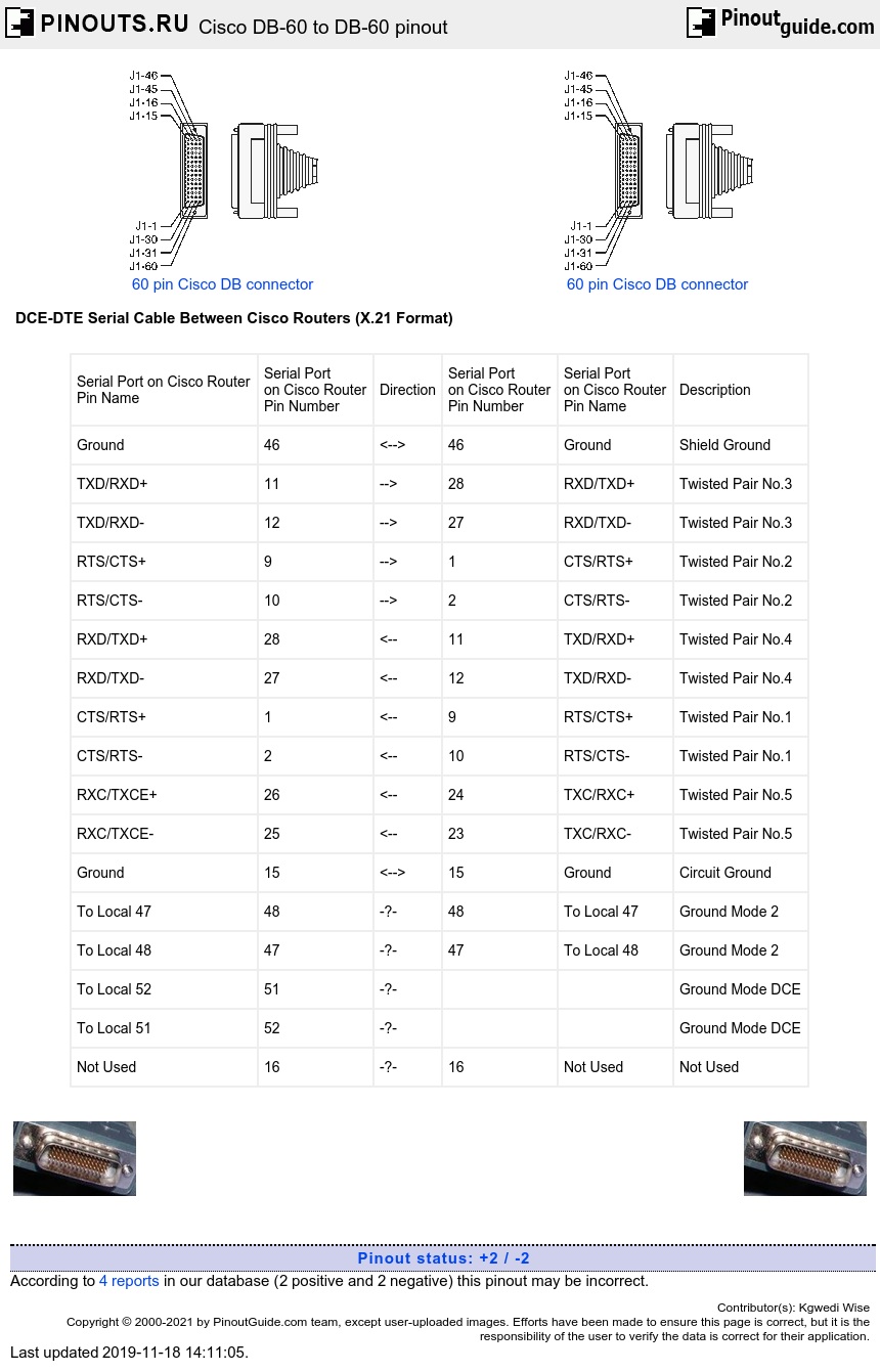
| Serial Port on Cisco Router Pin Name |
Serial Port on Cisco Router Pin Number |
Direction | Serial Port on Cisco Router Pin Number |
Serial Port on Cisco Router Pin Name |
Description |
| Ground | 46 | <--> | 46 | Ground | Shield Ground |
| TXD/RXD+ | 11 | --> | 28 | RXD/TXD+ | Twisted Pair No.3 |
| TXD/RXD- | 12 | --> | 27 | RXD/TXD- | Twisted Pair No.3 |
| RTS/CTS+ | 9 | --> | 1 | CTS/RTS+ | Twisted Pair No.2 |
| RTS/CTS- | 10 | --> | 2 | CTS/RTS- | Twisted Pair No.2 |
| RXD/TXD+ | 28 | <-- | 11 | TXD/RXD+ | Twisted Pair No.4 |
| RXD/TXD- | 27 | <-- | 12 | TXD/RXD- | Twisted Pair No.4 |
| CTS/RTS+ | 1 | <-- | 9 | RTS/CTS+ | Twisted Pair No.1 |
| CTS/RTS- | 2 | <-- | 10 | RTS/CTS- | Twisted Pair No.1 |
| RXC/TXCE+ | 26 | <-- | 24 | TXC/RXC+ | Twisted Pair No.5 |
| RXC/TXCE- | 25 | <-- | 23 | TXC/RXC- | Twisted Pair No.5 |
| Ground | 15 | <--> | 15 | Ground | Circuit Ground |
| To Local 47 | 48 | -?- | 48 | To Local 47 | Ground Mode 2 |
| To Local 48 | 47 | -?- | 47 | To Local 48 | Ground Mode 2 |
| To Local 52 | 51 | -?- | Ground Mode DCE | ||
| To Local 51 | 52 | -?- | Ground Mode DCE | ||
| Not Used | 16 | -?- | 16 | Not Used | Not Used |
This was deduced from two X.21 cables hooked back to back. For DCE side I had to add 2 extra wires (Pins 25,26) not used in X.21, and swapped most pin pairs. I currently use this cable between a Cisco 2520 and a Cisco 1601 at 1.5 Mb/sec.
Can be manufactured from a pair of Cisco X.21 cables. You may have to modify the DB60 end of one of them if both are the same DxE type.
The DCE end (MODE_DCE not grounded) needs to supply the clock, and shows in show controllers as DCE V.11 (X.21), clock rate 2000000 or similar.
The DTE end (MODE_DCE grounded) shows in show controllers as DTE V.11 (X.21) TX and RX clocks detected or similar.


 correct
 incorrect