
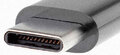
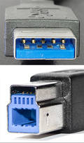
USB type-C to USB 3.2 cable
Full-featured USB-C cables that implement USB 3.1 Gen 2 can handle up to 10 Gbit/s data rate at full duplex. They are marked with a SuperSpeed+ (SuperSpeed 10 Gbit/s) logo. There are also USB-C cables which can carry only USB 2.0 with up to 480 Mbit/s data rate. All USB-C cables must be able to carry a minimum of 3 A current (at 20 V, 60 W) but can also carry high-power 5 A current (at 20 V, 100 W).
| USB-C 1 Signal | USB-C Pin | USB 3.2 Pin | USB 3.2 Signal | USB 3.2 Description |
|---|---|---|---|---|
| Ground | A1,B1,A12,B12 | 4,7 | GND, GND_DRAIN | Ground |
| Vbus power | A4,B4,A9,B9 | 1 | Vbus | Vbus power |
| Configuration channel. Shall be connected to Vbus through a resistor 56 kΩ | A5 | |||
| Vconn | B5 | |||
| USB 2.0 differential pair, positive | A6 | 3 | USB D+ | USB 2.0 differential pair, positive |
| USB 2.0 differential pair 1, negative | A7 | 2 | USB D- | USB 2.0 differential pair, negative |
| SuperSpeed differential pair 1 TX, positive | A2 | 6 | StdA_SSRX+ | SuperSpeed differential pair RX, positive |
| SuperSpeed differential pair 1 TX, negative | A3 | 5 | StdA_SSRX- | SuperSpeed differential pair RX, negative |
| SuperSpeed differential pair 1 RX, positive | B11 | 9 | StdA_SSTX+ | SuperSpeed differential pair TX, positive |
| SuperSpeed differential pair 1 RX, negative | B10 | 8 | StdA_SSTX- | SuperSpeed differential pair TX, negative |
| shield | shield | |||
Pins not mentioned are not connected. Pin A5 shall be connected to GND through a resistor 5.1 kΩ only (no Vbus connection) in standard-B cable.
Coaxial wire construction should be used for all SDP’s and there are no drain wires. The shields of the coaxial wires are connected to the ground pins. If shielded twisted pair is used, then drain wires are needed and shall be connected to the GND pins.
Pins B6 and B7 should not be present in the USB Type-C plug.
All Vbus pins shall be connected together within the USB Type-C plug. A bypass capacitor is required between the Vbus and ground pins in the USB Type-C plug side of the cable. The bypass capacitor shall be 10nF ± 20% in cables which incorporate a USB Standard-A plug.
Shield and all GND shall be connected within the USB Type-C plug on both ends of the cable assembly.
Maximum cable length is 2 meters.
 correct
 incorrect