Is my vehicle equipped with OBD-2?
On Board Diagnostics, OBD-II, is required on all automobiles and light trucks in the United States from 1996 onward. OBD-II is a set of specifications for monitoring and reporting on engine performance in modern automobiles. Diesel (compression ignition) vehicles were not required to support OBD until 2004. Some pre-2001 petrol vehicles and pre-2004 diesel vehicles have a 16-pin connectors but they may not be OBD-II or EOBD compliant.
Where is an OBD II connector?
Locating your OBD-II connector can be a difficult task as vehicle manufacturers tend to hide away the socket. Usually OBD-2 connector is located on the driver's side of the passenger compartment near the center console. Sometimes it's located in the driver's foot well, under the steering wheel, behind panels in the dashboard fascia and the central area between the driver's seat and the passenger seat. Some connectors have been located behind ashtrays, under the passenger seat and even over by the passengers door.
OBD-2 connector must have pins 4, 5 for ground connections and pin 16 for power supply from the vehicle battery.
The connector exists in two versions, type A for 12 Volt vehicles and type B for 24 Volt vehicles.
What is OBD DTC?
Prior to OBD, auto manufacturers did not standardize DTC's (diagnostic trouble code). OBD-I begins standardized DTC's OBD-II adds specific tests to determine the vehicles emission performance OBD-III adds more features, and is in the regulatory development phase.
If the vehicle's onboard diagnostic system detects a malfunction, a DTC corresponding to the malfunction is stored in the vehicle's computer, as well as realtime data from the sensors connected to the on-board computer. In addition, the OBD-II interface provides a means to clear the DTC's once maintenance has been completed. A service technician can retrieve the DTC, using a scan tool, and take appropriate action to resolve the malfunction. Prior to the advent of digital powertrain control modules, which is the technical enabler for the OBD feature, repairing a vehicle relied solely upon the technicians skill and service literature from the auto manufacturer.
OBD-II connector specifications
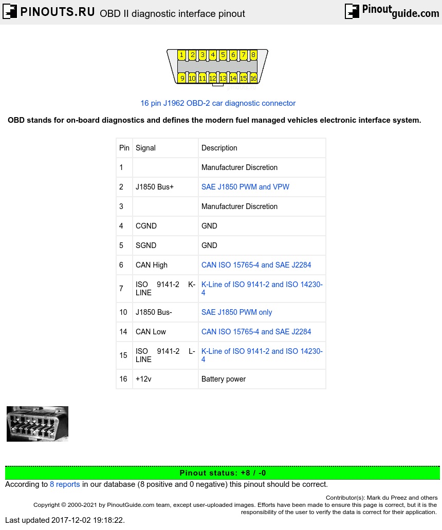
The OBD-II specification provides for a standartized hardware interface - the female 16-pin (2x8) J1962 connector. Unlike the OBD-I connector, which was found under the hood of the vehicle, the OBD-II connector is located on the driver's side of the passenger compartment near the center console.
Refer to related pinouts for vendor-specific OBD-2 pinouts.
| Pin | Signal | Description |
| 1 | Manufacturer Discretion | |
| 2 | J1850 Bus+ | SAE J1850 PWM and VPW |
| 3 | Manufacturer Discretion | |
| 4 | CGND | GND |
| 5 | SGND | GND |
| 6 | CAN High | CAN ISO 15765-4 and SAE J2284 |
| 7 | ISO 9141-2 K-LINE | K-Line of ISO 9141-2 and ISO 14230-4 |
| 10 | J1850 Bus- | SAE J1850 PWM only |
| 14 | CAN Low | CAN ISO 15765-4 and SAE J2284 |
| 15 | ISO 9141-2 L-LINE | K-Line of ISO 9141-2 and ISO 14230-4 |
| 16 | +12V or +24V | Battery power |
There are five protocols in use with the OBD-II interface, and often it is possible to make an educated guess about the protocol in use based on which pins are present on the J1962 connector:
OBD-2 protocols
SAE J1850 PWM (41.6 kbaud, standard of the Ford Motor Company)
pin 2: Bus-
pin 10: Bus+
High voltage is +5V
Message length is restricted to 12 bytes, including CRC Employs a multi-master arbitration scheme called Carrier Sense Multiple Access with Non-Destructive Arbitration (CSMA/NDA)
SAE J1850 VPW (Variable Pulse Width) (10.4/41.6 kbaud, standard of General Motors)
pin 2: Bus+
Bus idles low
High voltage is +7V
Decision point is +3.5V
Message length is restricted to 12 bytes, including CRC Employs CSMA/NDA
ISO 9141-2. This protocol has a data rate of 10.4 kbaud, and is similar to RS-232.
ISO 9141-2 is primarily used in Chrysler, European, and Asian vehicles.
pin 7: K-line
pin 15: L-line (optional)
UART signaling (though not RS-232 voltage levels)
K-line idles high
High voltage is Vbatt
Message length is restricted to 12 bytes, including CRC
ISO 14230 KWP2000 (Keyword Protocol 2000) used by most European and Asian manufacturers.
Alfa Romeo, Audi, BMW, Citroen, Fiat, Honda, Hyundai, Jaguar (X300, XK), Jeep since 2004, Kia, Land Rover, Mazda, Mercedes, Mitsubishi, Nissan, Peugeot, Renault, Saab, Skoda, Subaru, Toyota, Vauxhall, Volkswagen (VW) since 2001, Volvo to 2004
pin 7: K-line
pin 15: L-line (optional)
Physical layer identical to ISO 9141-2
Data rate 1.2 to 10.4 kbaud
Message may contain up to 255 bytes in the data field
ISO 15765 CAN (250kbit/sec or 500kbit/sec)
pin 6: CAN High
pin 14: CAN Low
Used in most modern vehicles.
Note that pins 4 (battery ground) and 16 (battery positive) are present in all configurations. Also, ISO 9141 and ISO 14230 use the same pinout, thus you cannot distinguish between the two simply by examining the connector.
OBD-II CAN bus
CAN bus used in Ford, Mazda, Volvo and most other cars since 2004. The CAN protocol is a popular standard outside of the automotive industry and is making significant in-roads into the OBD-II market share. By 2008, all vehicles sold in the US will be required to implement the CAN bus, thus eliminating the ambiguity of the existing five signalling protocols.
The CAN bus is simply a pair of wires, often twisted around each other, running around the vehicle and terminated at either end of the two-wire network with resistors of 120 Ohms. The only components connected to the CAN bus are the electronic control units (nodes). Other components, such as sensors, motors, light bulbs, switches, etc. are wired only to the electronic control units. Some vehicles have a CAN bus system along side the ISO/KWP2000 system. A vehicle which uses CAN bus for on-board diagnostics can only respond to an OBD-II request from a tester which uses CAN bus. From model year 2008 vehicle manufacturers must use the OBD protocol specified in ISO 15765, also known as Diagnostics On CAN.
Two wires of CAN bus, CAN-H and CAN-L, will have the same voltage when idle (about 2.5V), or a voltage difference of 2V when a signal is placed on the CAN bus. When a signal is placed on the CAN bus the CAN-H line is at a higher voltage than the CAN-L line. Each electronic control unit have its own CAN identity code, like an address (may respond to several CAN id codes). If an electronic control unit is to communicate to another it will need to know the CAN identity code of the recipient.
A simple check to see if the CAN bus is in use in a vehicle, and accessible via the OBD socket, is to connect a resistance meter across pin 6 and pin 14. Due to the combined resistance of the two termination resistors at 120 Ohms each the overall resistance should be read as 60 Ohms.
OBD-II provides access to numerous data from the ECU and offers a valuable source of information when troubleshooting problems inside a vehicle. The SAE J1979 standard defines a method for requesting various diagnostic data and a list of standard parameters that might be available from the ECU. The various parameters that are available are addressed by parameter identification numbers or PIDs which are defined in J1979. For a list of basic PIDs, their definitions, and the formula to convert raw OBD-II output to meaningful diagnostic units, see OBD-II PIDs.
 correct
 incorrect